SIMPLY LONGER
4
12/09/09
I had a change of mind and decided to work on the axle pumps next. I've had enough of cast iron dust for a bit!
As mentioned before, I'm not using the double acting pump designed by Martin Evans (although there is nothing wrong with it) but fitting twin single acting pumps instead as I think they will possibly be more reliable in the long term. Also if one pumps packs up there is still the other one to keep up the water level. I know the trend nowadays is to dispense with axle pumps on the larger locos and just rely on injectors but I prefer to have a pump that can slowly add water all the time you are running rather than banging a lot in all in one go with an injector.
The body of the pump is a fabrication from brass with bronze for the pump cylinders. The valves will be poppet type fitted with O rings to form the seal, similar to some clack valves available from suppliers. I also intend to fit PTFE seals to the rams rather than packing or O rings which seem to wear quite rapidly in this application.
The main part of the body is 1 inch square brass bar bored to take the two bronze cylinders and drilled and milled for the water passages and the poppet valves. The body is the full width of the frames and so acts as a substancial frame stretcher as well. The square bar was cut and faced to length in the four jaw chuck and then the two blind holes for the cylinders drilled and bored, again using the four jaw.

Boring the holes for the two pump cylinders
The cylinders were turned from 3/4 inch phosphor bronze bar and drilled and reamed 7/16" for the stainless steel rams, not an easy task as phosphor bronze is dreadfull stuff to drill! The two cylinders were then silver soldered into the brass body and the various passageways drilled and milled. The recesses for the valves were drilled and then enlarged with an ordinary endmill used like a D bit to give a flat bottomed hole.


The finished pump body with passeways etc. drilled
The inlet and outlet manifolds which will contain the poppet valves are just lengths of rectangular brass bar drilled in the appropriate places for the passageways and the fixing bolts. I did initially try to fit both the inlet and outlet valves in the bottom of the pump body which would have made them easy to get at but it would have made the whole thing very complicated so I have now put the outlet valves on top of the body as normal. Hopefully the design of the pump will become clearer once I have the valves made and can show the method of assembly!

Inlet and outlet manifolds. The flat plate is just a blanking plate to seal two passages milled in the body

Inlet manifold on bottom of pump body


Blanking plate and inlet manifold on top of pump body
This colourful cross section of the pump might explain the workings a bit better! The red bits are the poppet valves.

14/09/09
I made the valves yesterday from 3/8 inch hexagonal brass bar. Why hexagonal? The stems of the valves need to have three grooves machined in them to allow passage of water past them and using hexagonal bar makes it easy to index the grooves without having to use the rotary table!
The end of the bar was turned down to form the head and stem of the valve and then the hex bar removed from the chuck with the part machined valve still attached. The bar was then clamped in a machine vice and the grooves machined in the stem with a 1/8 inch round nose milling cutter. When the first groove had been machined it was simply a matter of turning the hex bar around one flat to machine the second groove, and again to machine the third.

Valve partly machined in the lathe

Milling the grooves in the valve stem
(Sorry for the quality of the above photos but they were taken with flash which reflected off the brass badly!)
After milling the grooves, the bar was returned to the lathe, the valve parted off, and the top faced off.
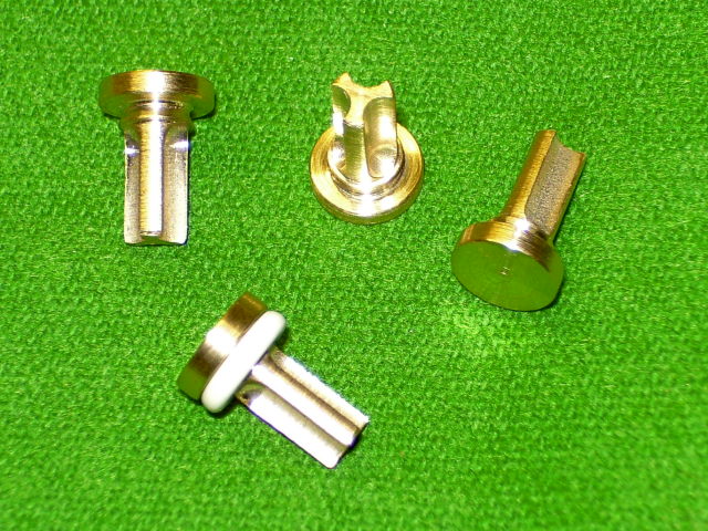
The finished valves, one with O ring fitted
26/09/09
The pump rams are stainless steel but I decided to fit a seal made from PTFE rather than the usual O ring. The seals are a double sided cup washer (similar to the old leather cup washers in bike pumps etc.). These were turned from PTFE and bored out either side to leave a thin edge on each end. The idea is that when pumping against boiler pressure the water will expand the thin cup against the bore and make a good seal (hopefully!)

Cup seals made from PTFE
The cups are fastened to the ends of the rams with a brass screw and washer with an O ring inbetween to seal the cup to the ram and stop any leakage at the join.


PTFE cup assembly
The final job on the rams was to drill and ream the ends for the cross pin and mill a slot for the eccentric arm.

Slotting the end of the ram
The eccentric straps are cast iron castings from Blackgates. I did think of fabricating these from bronze but I didn't have any suitable material and the castings were so cheap it wasn't worth bothering!
The castings were sawn in half to separate the end caps from the main body and the mating faces milled flat. I then stuck the two halves together with Loctite and drilled and tapped for the securing bolts. Gluing the halves together first before drilling made sure the holes lined up perfectly. To be on the safe side I fitted some temporary screws as well to hold the halves together during the subsequent machining
The straps were then chucked in the four jaw and the outside faces faced off and the straps brought to thickness. The inside bore for the eccentric was then machined. The original Simplex eccentrics are turned from 1-5/8" bar (or castings) but I only had 1-1/2 inch bar in stock. By very carefully setting up the straps in the four jaw I was able to bore them out to 1-3/8 inches instead of 1-1/2" enabling me to make the eccentrics smaller!

Boring out the eccentric straps
The outside edges of the straps were finished by milling in the vice for the lugs and using the rotary table for the curved bits. I milled the square edges of the lugs etc with both straps clamped together as a pair and a short length of bar in the bores to line them up. This made the job quicker and also meant both straps would be identical.

Finishing the outside of the straps
The final job was to mill the slot to take the operating arm. Again I machined both straps as a pair.

Milling the slot for the arm
The arms were made from 3/16 inch mild steel bar milled and filed to shape as a pair using filing buttons to shape the rounded end. The original Simplex ones are only 1/8 inch thick which, to me, doesn't give much of a bearing surface for the pivot pin in the pump ram. I'm going for long life under heavy use, hence the increase in thickness of the arm to 3/16 inch. The arms are held into the straps with three 6BA bolts and they are fitted with bushes made from bearing grade PEEK. I'm looking at making all joints in the valve gear etc. with replaceable bushes and pins to make future maintenance as easy as possible!

28/09/09
Today I machined up the eccentrics themselves from some oddments of 1-½" free cutting mild steel bar (left over from the Kennet). The end of the bar was faced off and centre drilled deeply so that I could support the outer end with a centre in the tailstock. Although the bits of bar were only a couple of inches long, the groove for the strap was going to be cut with a parting tool so I wanted the setup as rigid as possible to stop any chatter.

Machining the groove with a parting tool
Using a parting tool is fairly straightforward as you can machine the whole width of the groove with just the one tool but you have to make sure that the end of the tool is ground square and the tool is perfectly square to the bar. After setting up the tool in the toolpost I took a very slight cut on the surface of the bar to make sure that the tool was cutting the full width of the blade. If it only takes a shaving off one side then the tool is obviously out of square to the bar and needs resetting!
The groove was turned to nearly the right size and then the strap tried in place to check the fit. The diameter of the groove was then skimmed until the strap was a good fit i.e. free to move but with no play.

Checking the fit of the strap
The eccentric was then parted off, faced to the thickness required and the process repeated for the second one.
Both eccentrics were then chucked in the four jaw and offset for boring the hole for the axle. Before this I marked out where the centre of the axle would be on the eccentric and made a little centre pop. This centre pop was then set to run true and I knew that the hole would be in the right place. The axles are 3/4 inch diameter so the holes were drilled out to 1/2" (my largest drill) and then bored out to final size, checking with a plug gauge.

Boring the eccentric for the axle
The eccentrics are secured to the axle with a 2BA grubscrew so next the holes for these were drilled and tapped and that was the eccentrics finished. All that was needed now were the two pivot pins to fasten the straps to the pump rams. These are my favourite type of pin i.e. a hollow silver steel pin with a bolt through the middle to hold it in place. So much easier to make than trying to thread the ends of the pin for nuts etc.!

The finished eccentrics and straps
It looks like the next job will have to be the wheels and axles! The chassis will be on our club stand at the Midlands ME Exhibition next month so it would be nice to have a complete rolling chassis for then.
Previous PageNext Page