SIMPLY LONGER
3
03/08/09
The next part was the sliding horn assembly that gives the axle it's sideways movement. This was another fabrication from brass and consists of a curved base plate that bears on the top of the curved guide in the frame with four pieces of brass bar silver soldered on to form the sides of the horns.
The curved base plate was cut out from 1/4" brass bar and then milled to shape using the rotary table set up again.

Milling the curved base to shape
The four vertical pillars to form the sides of the horns were cut from 1" square bar sawn down the middle as I didn't have any 1" x 1/2" ! To help position these on the base I temporarily glued a piece of brass bar to the base and clamped the pillars to it. I then secured the pillars with brass screws and finally silver soldered them in place.

Clamping the pillars in position before securing them with screws

Silver soldered together
The silver soldering caused the base to distort quite badly so I milled it flat again to give a true surface for setting up for the machining of the pillars. The majority of the excess on the pillars was cut off with a slitting saw in the mill and then the curved sides milled with the rotary table to give a nice 'easy' fit in the curved frame guides. No point in making these a precision fit as they would probably jam.

Milling the pillar sides to fit the curved guides
The inside edges of the pillars that take the axle boxes had to be machined parallel and the easiest way to hold the sliding horns was to use the main horn/stretcher as a jig. This could then be easily held in the machine vice. The sliding horn assembly has a couple of bolts in the top that slide in curved slots in the top of the main stretcher. These stop the sliding horns falling out when the loco is lifted up off the track and were ideal to clamp the sliding horns in place whilst the inside edges were milled.


Milling the slots to take the axleboxes

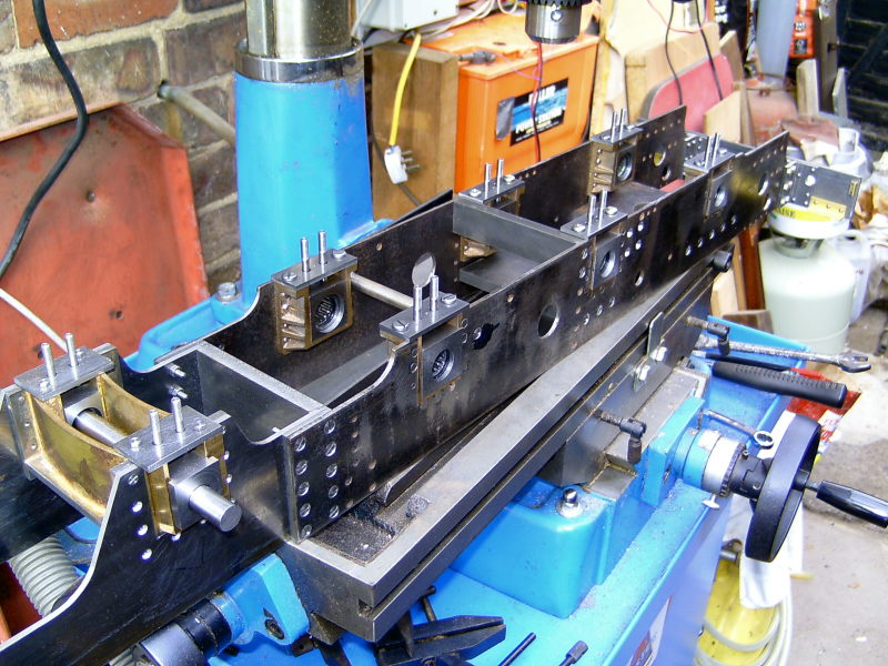
Sliding horns finished and in position
The axleboxes will be machined from mild steel bar and will be fitted with needle roller bearings. These might have to wait a bit as my big 4 jaw chuck (which I'll probably need to use) has a wheel turning jig in it at the moment that I was using to finish machine the main driving wheels. I started machining the wheels some time ago so I'll have to finish them before I can use the chuck for anything else. Problem is, I can't remember how far I got with the wheels. It seems so long ago!
09/08/09
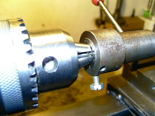
The axleboxes were machined from 1 inch square mild steel. Two lengths were sawn off and then faced off in the lathe to the right length. The small 4 jaw chuck proved to be adequate to hold them so I won't need to free up the big one just yet! The axleboxes were then milled to fit the horns leaving a flange on the outside. They were then drilled and bored out to take the needle roller bearings which need to be a press fit. The outer shells of these bearings are very thin and they need to be pressed into the housing to make sure the shells are truly circular. I miked one up before fitting and the outer shell was slightly oval.

Milling the flanges on the boxes

Boring out for the needle roller bearings
Before finally fitting the bearings I drilled and tapped the axleboxes for the two spring pins and shaped the inside edge of the flange so that the boxes can tilt without jamming. Normally the inside edges are radiused using a rotary table (or even filed by hand) but I saw an article some time ago that recomended making the edges 'V' shaped rather than curved as they are less likely to jam when the boxes tilt. I decided to give this a try as it is much easier to machine a Vee than a radius! The machine vice is on a rotary base so I just angled the vice 5 degrees either way amd milled each half of the flange. I left a small flat on the point of the Vee rather than make it sharp to give a bit more bearing surface to bear against the side of the horn.

Milling the V shape on the inside edge of the flanges

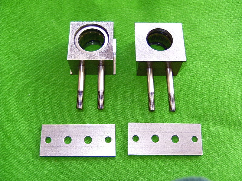
Finished axleboxes and hornplates
The hornplates are just pieces of 1/8" mild steel drilled for two securing bolts and clearance holes for the spring pins. Just need the springs and the spring plates to complete the assembly.

Fitted in place with dummy axle
I've made a start on the main axleboxes today which will be machined in the same way as the trailing ones. I've got some lumps of cast iron for these that came with the bits. These have already been milled to the outside dimensions so it would be a shame not to use them. They could do with being a bit longer really as there won't be much at the bottom to screw in the spring pins after they are bored for the needle roller bearings but they should be ok.
29/08/09
A bit of a gap since the last update but I've been busy in the garden and also tiling a downstairs loo for a friend!
The main axleboxes are now complete and ready for the axles and were machined in exactly the same way as the axleboxes for the trailing axle. I pondered on the problem of getting the bores for the needle roller bearings in exactly the same place on each pair of boxes to ensure that the axle would be perfectly square across the frames. On previous locos I've soldered the boxes together back to back and bored them as a pair but this wouldn't work this time as the bores have a step in them so cannot be bored all the way through. A method often given is to chuck the axlebox in the four jaw, set to run true and then bore for the axle or bearing. The box is then removed by loosening two jaws, say one and two, and the second box chucked and the same two jaws tightened to hold it. In theory the second box will be in exactly the same position as the first and so the bore will be in the same place. The jaws on my big four jaw are a bit stiff and can move when the opposite one is loosened so I did not trust this way of doing the job.
I decided to drill and ream a 1/2" pilot bore in each axle box using the milling machine and then set each box to run true in the chuck using a length of silver steel in the pilot bore and a dial gauge before boring to final size. To set the boxes up in the mill they were held in the machine vice with a stop on the vice to make sure each box was clamped in the same position. For each box the front face of the box was clamped against the fixed jaw of the vice and the top against the fixed stop. They were then drilled and reamed to 1/2" bore. This method ensured that the pilot bore would be exactly the same distance from the front and top edges for each box and hence the axles would be perfectly square across the frames. The boxes were then transferred to the four jaw and bored out to clear the 3/4" axle and counter bored to take the needle roller bearings.

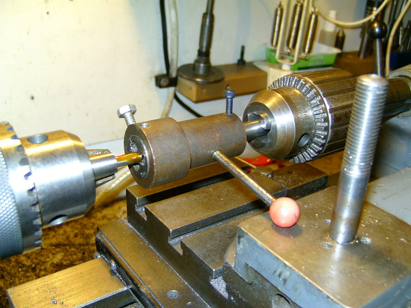
Setting the box to run true using a silver steel bar in the pilot bore
The boxes then needed drilling and tapping for the spring pins but first I needed the hornstays which I use as a jig for drilling the boxes for the pins.
These are just plain strips of 1/8" mild steel cut and milled to size. One was marked out and drilled for the spring pins and the fixing bolts and then used as a jig to drill the rest. To position the stays on the bottom of the axleboxes I cut a strip of steel the width of the axlebox slot and bolted it to one of the hornstays. This was then clamped in position on the horns and the fixing holes spotted through to the horns. I only had to use the one stay as a drilling jig as they were all identical.

Hornstay with spacer attached to align it on the horns

Spotting through the fixing holes to the horns
Once all the hornstays were made they were temporarily bolted in position. The axleboxes could then be clamped in position in the horns and the holes for the spring pins spotted through the stays onto the bottom of the boxes. The boxes were then drilled and tapped 2BA for the pins. I tapped the holes with the boxes held in the machine vice on the mill and the tap held in the chuck to ensure the tapped holes finished up vertical to the bottom of the boxes. Don't want the pins leaning at all angles!
The spring pins are 3/16" stainless steel. These were cut to length, each end faced off in the lathe, and then each end threaded 2BA using the tailstock die holder. An easy way to get the threads all the same length is to chuch the pins with a certain length protruding from the jaws. If the die is run right up to the jaws every time, the threaded part will always be the same length.
I usually use either the 3 jaw chuck or a drill chuck to hold the pins while threading as I find that a collet (well, mine anyway) won't grip the pins tightly enough and they slip leading to scoring of the pins.

Threading the ends of the pins
The pins were screwed tightly into the boxes and then the needle roller bearing pressed in place. Job done!
Completed axleboxes ready to fit
Next, axles and wheels!
Previous PageNext Page