,,,,
Kennet
3
17/12/2007
At this point I decided to fit the motor and belt. The pulley was fitted to the motor and the motor placed in position on the base, the pulleys lined up, and the motor mounting holes marked out. These were drilled and tapped and the motor bolted in place.
The drive belt is a round section plastic one which needs to be cut to length and then joined by melting the ends and pushing them together. To get the right tension in the belt the actual length around the pulleys is measured and then multiplied by 0.92. The ends of the belt were cut square with a sharp knife and the ends melted by holding them near to a gas flame. The ends were then pushed together using a scrap of brass angle as a jig to keep the belt in line as the plastic set. The excess plastic was then trimmed off with the knife.

The belt just after joining
I actually had to redo this joint as it peeled apart when bent. I obviously hadn't got the plastic quite hot enough the first time and it hadn't fused together completely. It needs to be quite 'runny' to join properly.
The belt was then fitted and I must admit it seemed very tight but I'm sure I had measured it correctly. The belt material is quite 'stretchy' though so it probably needs to be tight to stay on!
The motor was switched on and - nothing! It would not run at all and just buzzed. It would run without the belt on but did not seem to have any power. Looks as though I picked a duff motor! Fortunately I have another 1/8 hp 1440 rpm motor that came off the old Flexispeed lathe. This will probably be better anyway as it has a reversing switch which the other motor did not have. I'm not sure why it should be necessary to run the motor in reverse when grinding but the plans do actually call for a reversible motor.
To use this new motor I had to redrill the mounting holes in the base as they were in different positions. Also this motor has a larger diameter spindle so I had to rechuck the pulley and open out the bore to ½". Fortunately the belt length was still ok so I did not have to alter that.
This time everything worked ok on test but the grinding spindle seems to get rather hot after only a short time which would suggest some friction somewhere. Mind you, it is spinning at something like 5000 rpm.

The motor will get a repaint later!
That's the base and spindle finished so it's on with the table assembly.
First item is the table support. This is another iron casting which requires the base and both ends cleaning up and a 3/4" wide slot milling in one end. The base and ends were flycut on the lathe cross-slide again and the slot milled in the micro mill. This last operation was a bit of a struggle but was managed eventually with a lot of noise and vibration. Good job the neighbours were at work!

Flycutting the base

Flycutting the ends

Milling the slot in one end
18/12/2007
The table support casting has a length of 3/8" wide steel screwed to the bottom which slides in the slot in the base and a lever operated clamp to lock it in the desired position. This enables the table to be moved towards and away from the grinding wheel to suit whatever tool is being sharpened.
The clamp is simply a slab of steel with a threaded stud loctited in which goes up through a hole in the casting and a pin to stop it turning when the lever is tightened. The clamping nut is just a length of bar with an internal thread and fitted with a lever carrying a plastic ball on the end.

Table support with clamp components

Completed table support
The next major component is the actual main table so it's on with that next time.
22/12/2007
The more I looked at the table casting the more I realised it was going to be a bit of a nightmare to machine! It's a very awkward shaped casting because of the long boss in the middle with which it clamps to the table support. This would make it very difficult to hold the casting for any machining operations on the top surface.
I started off with the easy bit - truing up the two pads on the underneath of the casting which take the bracket holding the intermediate table stop bar. These were machined by clamping the casting onto the milling table and cleaning up the pads with an endmill.

Cleaning up the mounting pads for the stop bracket.
Then followed a period of head scratching as to how on earth I was going to cut the long slot which runs the whole length of the casting on the top face. This slot is to accept a length of 3/8" wide steel fastened to the bottom of the intermediate table so that the intermediate table can slide across the main table from side to side. The top slide has a similar arrangement to enable that to slide backwards and forwards on the intermediate table. The top-slide has a guide strip running in a slot in the top of the intermediate table.
The slot would have to be machined a little over 11 inches long and there was no way I could do that in one go - it would have to be done in two stages. Also, I would have to try and machine it in the lathe as it would be very difficult to mount the casting face upwards on the milling table due to the boss. I still wasn't sure it would be that easy to mount the casting on the lathe top-slide!
Eventually I decided that if I machined one long edge of the table casting flat I could use this as a guide when the slot was being machined in two stages. If a suitable straight edge was fastened to the lathe cross-slide and the machined edge of the casting was clamped against this, the casting could be moved along the straight edge without loosing alignment. Maybe.
The problem then was how to machine one edge of the casting straight? I had the same problem of not having enough travel on either the lathe of the mill to do it in one go - again it would have to be machined in two bits! I decided to use the straight edge idea here as well. A length of square steel bar was clamped to the casting along the opposite edge to that I was going to machine to form a guide. The casting was then clamped vertically to the milling table and the first half of the edge macined flat. The casting was then slid along the table (the straight edge keeping it level) and the second half of the edge machined.
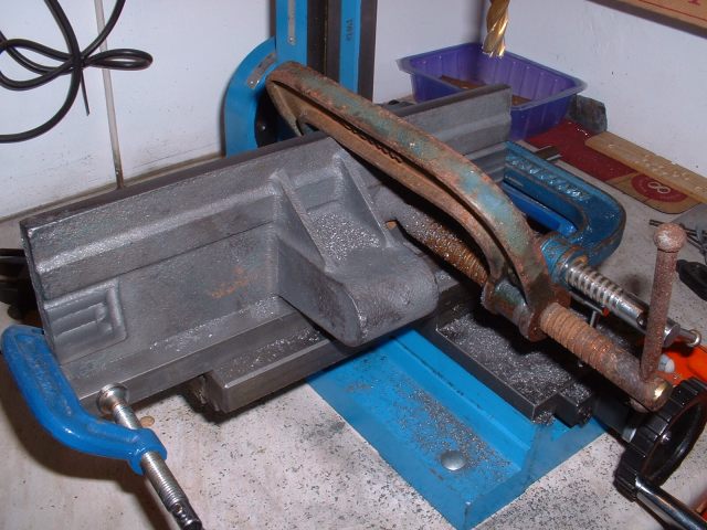
Milling the edge of the table straight
I now had my straight edge on the casting. However, after more thinking, I eventually came to the conclusion that milling the slot was just not going to be practical with the equipment I had at home. It was still going to be very difficult to mount the casting on the cross-slide so that the slot could be milled. Oh bother! The problems you get when you don't have adequate machinery!
Then I had a brainwave! (it does happen occasionally!). Why not cut the slot in the bottom of the intermediate table rather than in the main table and fasten the 3/8" guide strip to the main table instead. The intermediate table is just a flat slab of cast iron so is very easy to clamp to the milling table. The slot will also be shorter, although still too long to machine in one go. I can still use my straight edge idea to machine the slot in two bites. This change of design means that the slot and guide in the top-slide and intermediate table will also have to be reversed but I can't see a problem with that. It will just mean that the slot in the top-slide will have to be moved across about ½" to clear the stud for mounting the various tool holders.
Having decided on a solution to the slot problem I carried on machining the main table. The boss needs a ½" hole drilling and reaming through it for the bolt that clamps it to the table support and this was done in the lathe by clamping the table vertically to an angle plate on the cross-slide. A piece of steel bar was used under the edge of the table to raise it to the right height.

Drilling the hole in the table boss
Next task was to machine the side of the boss where it bolts against the table suport and this was done in the mill using an endmill. Unfortunately, the endmill was too short to machine the bottom part of the boss so I improvised and used a woodruff cutter to do the last bit.

Machining the last bit of the side of the boss with a woodruff cutter
The other side of the boss only has to be machined about halfway down so just the endmill was fine. The endmill was also used to machine the little lug at the top of the boss which carries a line to read against the brass degree plate fastened on the end of the table clamping bolt. This shows the angle that the table is tilted to the horizontal.

Machining the second side of the boss and the lug
Whilst the mill was set up I cleaned up the other edge of the table and also the ends. This isn't really necessary but I thought I would do it anyway.
Incidentally, the eagle eyed amongst you may have noticed that the mill has moved. I decided to temporarily move it down to the kitchen and sit it on one of the worktops over the Xmas period. This was so I can carry on with any noisy machining without upsetting the neighbours too much! The noise won't carry as much from the kitchen. Once they've gone back to work in the New Year I'll move it back upstairs.
Inbetween machining operations on the table I had a few breaks and made a few small bits which involved just fairly simple turning jobs on the lathe. The main item was the clamping bolt for the table along with the clamping nuts and washers. The bolt has two different diameters. The smaller diameter fits through the slot in the table support casting and has a flat sided boss in the middle which slides in the vertical slot in the support. This enables the bolt to move up and down in the support to alter the height of the table but without the bolt being able to rotate. The larger diameter fits through the table boss and the table can rotate about this and be clamped at the required angle. The end of the bolt also has two flats milled on it which fit through a thick washer shaped to fit. The washer was quite fiddly to make as the central hole has to be elongated to fit over the flats of the bolt so that it can slide but not rotate. This washer carries a brass scale which indicates the tilt of the table. The flats on the washer and the centre of the bolt ensure that the scale does not move when the table is tilted. I am sure there is an easier way to do this but still, I've done it now!

Table clamping bolt, nuts, and washers plus some smaller clamping screws
<Previous Page......Next Page>